Contents:
Step-by-step instruction how to make these, with some experiments after completion:
Requirements
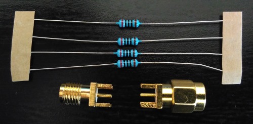
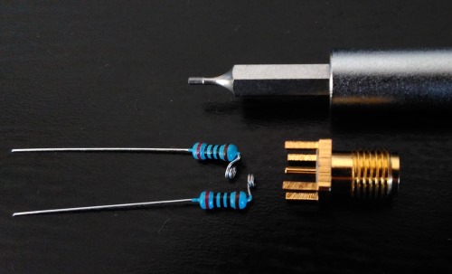
- 4x 200 Ohm resistors;
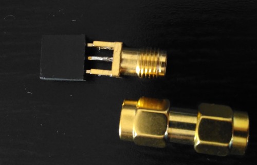
- SMA female PCB connector;
- SMA male PCB connector (these are quite rare);
- some tape or thin plastic sheet for isolation (not shown above);
- heat-shrink tubing (about 10 mm diameter, not shown above).
I’m using through-hole resistors because I have a lot of them in stock and no SMDs of required value.
With SMD resistors building can be simplified (no need for isolation), and will not be as fun as I wanted it to be.
For high-frequency applications you will most probably use SMD resistors and copper shielding, but I’m limited with tools up to 50 or 60 MHz at the moment.
Through-hole resistors have their own merit though. Four 0.25 Watt resistors in parallel can handle up to 1 Watt of power coming from a device under test. This might be important when measuring noise from a power supply for example.
Building process
I used a piece of plastic from plastic L folder for isolation.
First cut it to size of SMA connectors (squares 6mm x 6mm) and mark the center. Two pieces required per terminator.
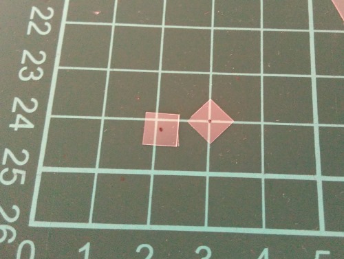
Then cut central holes and cutouts. put each isolator onto each connector.
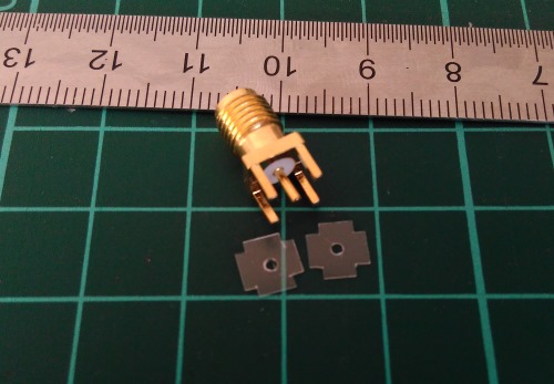
In order to simplify soldering to central pin, I made two turns on resistors’ leads. 0.9mm hex bit from screwdriver set came in handy.
Solder a pair of resistors to each connector. Make sure you didn’t lost isolators in the process.
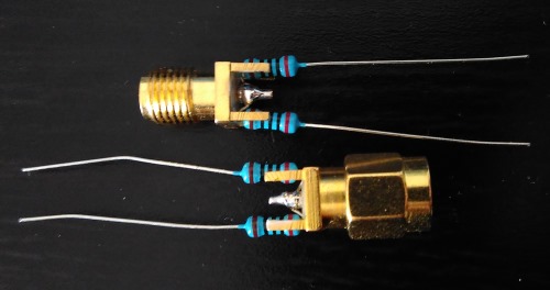
Next step is to solder connectors back to back.
- fix them in vice or “third hand” or any kind of jig;
- bend resistors away a bit to get access to central pins for soldering;
- make sure connectors aligned properly and there is enough space to put resistors in place on later step;
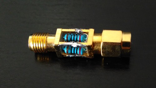
- solder central pins together;
- solder rest of connectors’ pins together - only small amount of solder required - try not to overdo it;
- put resistors in place, bend remaining leads to the side and solder them to connector pins.
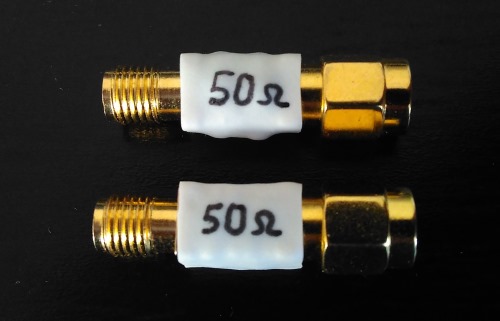
As for my mistakes, on a first terminator I put a little bit too much solder (as you can see on a picture below), and for second terminator I misaligned connectors a bit, so it was looking bent a little before applying heat-shrink.
Now put some heat-shrink tube on it to hide your soldering to make it fancier to write a value and it’s done.
Evaluation
First, measure the resistance with multimeter. I got 49.6 Ohm measured, which falls into 1% precision of resistors I used.
Resistor values matches quite well among the batch, so there is no chance to pick different values from single batch. I was thinking about putting one 220 Ohm resistor along with three of these slightly undervalued 200 Ohm resistors, but it would bring me to 50.8 Ohm, which is slightly worse.
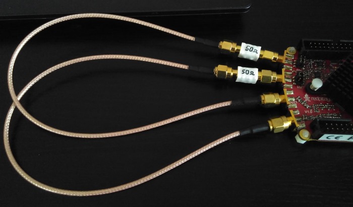
Next thing to do is to look at frequency response. So here is simple setup with RedPitaya.
And uncalibrated output looks like this:
I was not expecting anything fancy over 50 MHz due to RedPitaya’s 125 MHz sampling frequency. Below that it looks good enough (don’t forget there is calibration step before switching device under test in real use).
Then I became curious about what can be achieved with variable resistor. So I made the following setup:
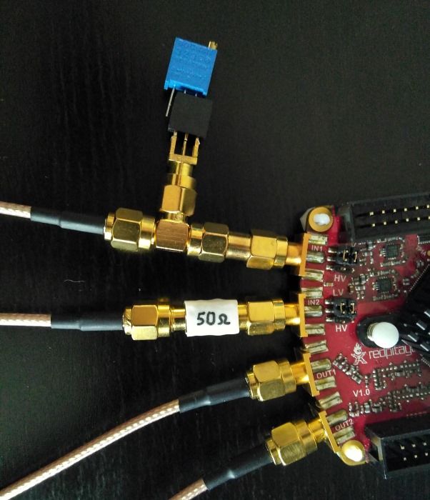
There is 10-turn pot connected through DIY 0.1 inch to SMA connector. You can consider it as a bonus part of this post :)
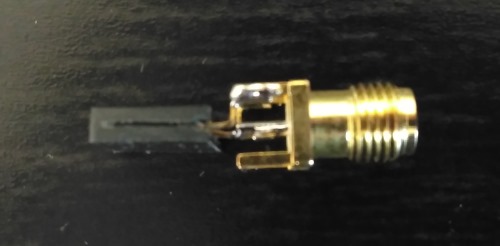
It makes sense to have such a thing with male connector, but they are harder to obtain. Gender changer connector can be used when needed.
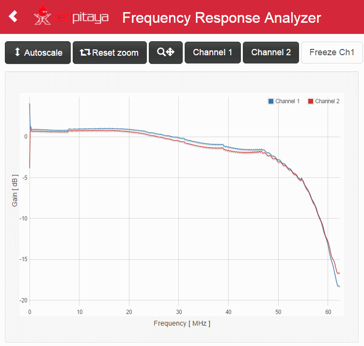
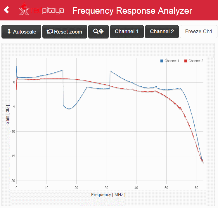
After playing with a pot for a while, I’ve got this picture:

Channel 1 (blue), where pot is connected, looks a bit more linear to me. After measuring a value on the pot, I found it is a bang on 47 Ohm. Wow. It’s kind of proof that it’s possible to go with single 47 Ohm standard value resistor for termination.
But beware. I took some 47 Ohm value resistor and put it in. It has 46 Ohm when measured with multimeter and gave me the following picture:

Just for kicks, here is frequency response with 68 Ohm resistor:
So much for this post.
